Accelerometer

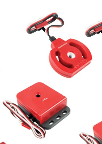
Accelerometers are complex sensors that can be used to detect the acceleration of a robot. This can be used for multiple functions, such as calculating the robot’s velocity. This function could then be used to determine if the robot ran into an object, due to the robot’s sudden loss of velocity. The robot has three axes on which to determine direction: the x-axis and the y-axis, which determine if the robot is going left, right, forward or backwards, and the z-axis, which measures up and down movement.

Each axis has its own value, which changes depending on the velocity of the robot. For the x and y-axis, when the robot moves in the direction of the axis that the arrow on the sensor is pointing to, the value will increase, and when going in the opposite direction, the value will decrease. For the z-axis, moving up will cause the value to increase, and moving down will cause it to decrease. The accelerometer also has a jumper attachment, which will increase the sensitivity of the sensor from +2g to +6g. The +6g mode is able to detect smaller changes in acceleration, but the +2g mode is more reliable when the the robot makes rapid changes in velocity.

Ultrasonic Range Finder

Ultrasonic range finders are unique sensors that use high-frequency sound waves to detect objects. The range finder is then able to measure the distance between the object and itself, and the robot can be programmed to react accordingly. This can be used to avoid bumping into walls or other robots, without the need to hit it, as would be needed with a bumper or limit switch. The frequency waves have a measuring range of 1.5 inches to 115 inches, which is over 3/4 the length of a standard VEX field.

The way that the ultrasonic range finder works is almost exactly the way that animals such as bats or dolphins use echolocation, or how a submarine uses sonar. The range finder sends out high-frequency waves that travel through the air. When the waves hit an object, such as a wall, the waves bounce backwards as an echo. The sensor then detects the returning sound waves and calculates the time it took for the sound to return. The longer the time it takes, the farther away the object. However, the ultrasonic range finder has troubles detecting softer objects, as the sound waves will be absorbed into the object and not return to the sensor.

Line Tracker

Line trackers are useful tools in autonomous control for detecting changes in light. They work by shining an infrared light onto a surface. An sensor then detects the intensity of the light that bounces back, and translates it into a numerical value. Since darker colors absorb more light than lighter colors, the data value will be different depending on the shade. Normally, lighter colors will have a lower value, while darker colors will have a higher value. Line trackers are analog sensors, which gives them a higher data range compared with digital sensors. The data range for a line tracker is between 0 and 4095.

The main use for line trackers, as stated in the name, is to track lines. Having a light colored line on a dark colored surface or a dark colored line on a light surface is recommended, as the bigger the contrast between colors, the easier it is for the sensor to differentiate between the two. In most VEX competitions, white reflective tape is set in various places on dark gray tiles, which makes it easy for the line tracker. The most common setup to following a line is to use three line trackers as shown in the image above. When the middle line tracker sees the tape, it knows that it is on the right path, and the robot will continue to advance forward. However, if either the left or right sensor detects the tape, the robot will slightly turn in the opposite direction until the middle sensor is the only one that sees the tape.

Potentiometers and Encoders

Encoders and potentiometers can be some of the most useful sensors for autonomous control, as they can be used to measure the distance a part moves. This is done by measuring the axle rotation of a shaft, which is inserted inside of the encoder or potentiometer. While both are similar, encoders and potentiometers each have their strengths and weaknesses, and knowing when to use them can be vital in running a robot.

Inner workings of an encoder

With the release of the V5 Smart Motors, encoders have been inserted into the motor itself, eliminating the need to attach a separate encoder, whose bulkiness proved troublesome when attempting to fit on the shaft. However, the working of the encoder itself remained the same. The axle shaft is attached to a circular disk with slits inserted in the edges. As the shaft rotates, light filters through the slits into a light sensor. The spaces in between the slits blocks the light, and allows the light sensor to determine the rotation and direction of the shaft. Encoders are most often used for the drive trains of robots, which offers a more accurate distance for the robot to travel, rather than using a timer.

Potentiometers have their own way of measuring the rotation of a shaft. When the shaft running through the potentiometer is turned, the resistance on the electical current running through the potentiometer increases, causing the voltage returning to the brain to change. The brain then is able to translate the voltage change into rotation degrees. This way of measuring rotation is more accurate than the encoder’s disk, but only is able to work up to 250 degrees. This is why potentiometers are used more often on mechanisms that have a limited rotation, such as an arm.

Vision Sensors

With the introduction of the V5 kits came the vision sensor. It works as a camera, and can be used to detect colored objects and react accordingly. The camera is able to detect seven different colors at once, which can be useful, as most game objects in the VEX competition are different colors. Vision sensors may be more complicated to program and use than touch sensors, but they also can be used as a more advanced way to enable the robot to sense where it is on the field. One of the most useful features of the vision sensor is it’s ability to not only locate a certain color, but to be able to determine it’s position on an X Y coordinate plane. This can be used to detect a scoring object, and then automatically aligning the robot in order to pick up said object. By tilting the camera, this feature can also be used to determine distance, by using trigonometry.

In order to register a color on the vision sensor, go to the vision configuration window on the VexCode program. By connecting the vision sensor to a power source such as the brain, as well as hooking it up to the computer, the camera view should be visible on the configuration window. By placing the colored object desired to be registered in front of the camera and pressing the freeze button, clicking the color wanted and then pressing set should register it in the camera’s memory, which can then be used in the program.

Touch Sensors

Touch sensors are some of the easiest sensors to program and use. When pressed, touch sensors will activate and send a signal to the brain of the robot. The two types of touch sensors are the bumper switch and the limit switch. They may have similar functions and program, but they each have their own intended purpose. A bumper switch is usually used to detect when a robot hits a wall, or to be touched manually in order to start an autonomous function. A limit switch is more likely to be used to stop an arm or other moving feature on the robot when it has reached the point that it should stop. Either way, touch sensors are a helpful tool, especially for beginner teams.

A touch sensor is a digital sensor, and either has a value of 0 or 1. While the bumper or limit switch is not being pressed, the value that it sends to the brain is 0. When it is pressed, the sensor will send out a 1. This is a simplistic idea and can be used for simpler functions, such as in the program above, where the robot will drive forward until the bumper switch is activated, most likely from hitting a wall. Once the bumper sends out a signal of 1, the program then proceeds to stop the drive motors.

Design a site like this with WordPress.com
Get started